Arduino Uno Bare Metal Programming
I discovered the Arduino boards several years ago, played around with them occasionally, but never full got the hang of it. I didn’t see lots of value in simply replicating 1:1 pre-made finish project, schematics and code snippet from tutorial or books. I always wanted to understand how the things work internally and if I encounter blockers, be able to figure out a solution on my own.
Because I have mostly mechanical and software engineering experience, electronics seemed complicated to me. I learned the electronics basics in my technical high school, but most of that knowledge is already gone, expect the Ohms law.
So, I wanted to learn more about bare metal programming and C programming in general. Many of the programming languages I know are based on C and share syntax or other similarities, like C#, Python or Typescript. This time I wanted to dive deeper into the topic with some low level memory management programming.
While I learned everything I could about pointers and bitwise operations, I also wanted to play around on a real microcontroller. This is how my journey began with bare metal programming on the Arduino Uno ATmega328P microcontroller.
Getting started
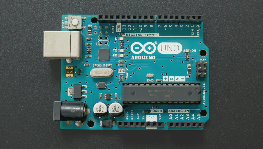
A typical “Hello World” example in microcontroller programming is a blinking LED. In many cases the Arduino Uno board has already a built-in LED. This LED is connected to a digital pin and its number may vary from board type to board type. On my board the digital pin 13 was assigned to that LED (can be used with the constant LED_BUILTIN).
By using the Arduino IDE you can easily write the blink example in a new sketch file like this:
void setup() {
  // initialize digital pin LED_BUILTIN as an output.
  pinMode(LED_BUILTIN, OUTPUT);
}

// the loop function runs over and over again forever
void loop() {
  digitalWrite(LED_BUILTIN, HIGH);  // turn the LED on (HIGH is the voltage level)
  delay(1000);                      // wait for a second
  digitalWrite(LED_BUILTIN, LOW);   // turn the LED off by making the voltage LOW
  delay(1000);                      // wait for a second
}
It consists of a setup and a loop function, initialized the pin and toggles the LED on an off with a delay. How difficult can it be to write the same functionality in C without any abstractions or helpers? To tackle this question you first need to understand the basic functionality of a microcontroller.
How does a microcontroller memory work?
Every microcontroller has a reserved memory section (called registers or ports) which are essential to work properly. The free memory section can be used for your stored data in variables and your code.
A register consists of 8 bits in the AVR microcontroller. The bits are counted from right to left, starting with zero. Bit 7 is also known as the Most Significant Bit (MSB). Bit 0 is also known as the Least Significant Bit (LSB).
The content of the register shown above can be also specified as:
binary notation: 0b10110011
decimal notation: 179
hexadecimal notation: 0xB3
Quick refresher on C pointers
A pointer is a variable that stores the memory address of another variable as its value. A pointer variable should have the same data type as the pointing variable, to ensure enough bytes for reading the variables value.
Pointer can also directly store memory address without pointing to a variable. C allows you to have a pointer on a pointer and so on. For more details on that topic, there are tons of tutorials online how to use them.
Accessing the registers
The registers are normally accessed byte-by-byte, so the entire byte of the register is always read or written.
To check whether a specific bit is set or not you have to use a bit mask. Setting or deleting is done on individual bits of the register with a suitable write bit mask, because the other bits should remain unchanged, since they may control certain functions in the microcontroller.
Set a bit of a register
Let’s assume that bit2 of a register should be set. The other bits of the register should not be changed. This can be achieved by bitwise OR operation to the register with a bit mask.
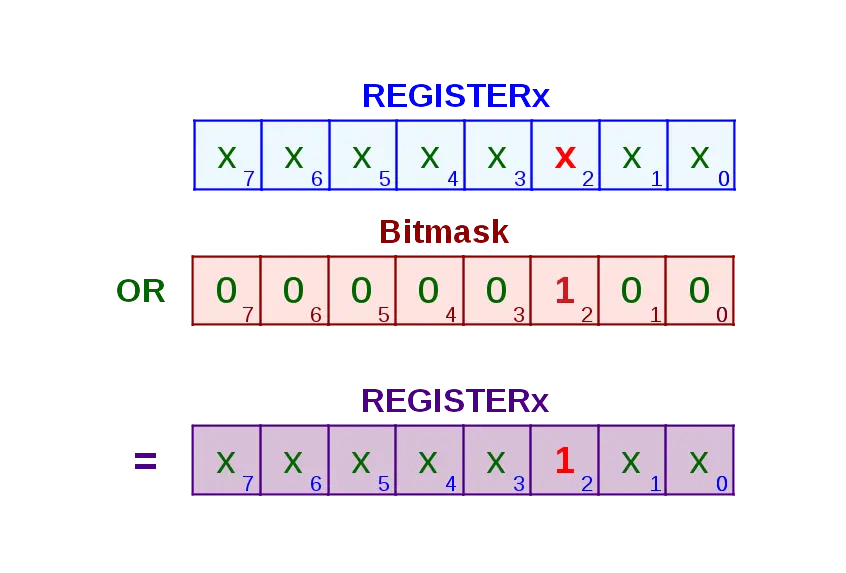
This can be achieved with the following code:
REGx |= 0b00000100;
Delete a bit of a register
Let’s assume that bit2 of a register should be cleared. The other bits of the register should not be changed. This can be achieved with a bitwise AND operation of the register with a bit mask.
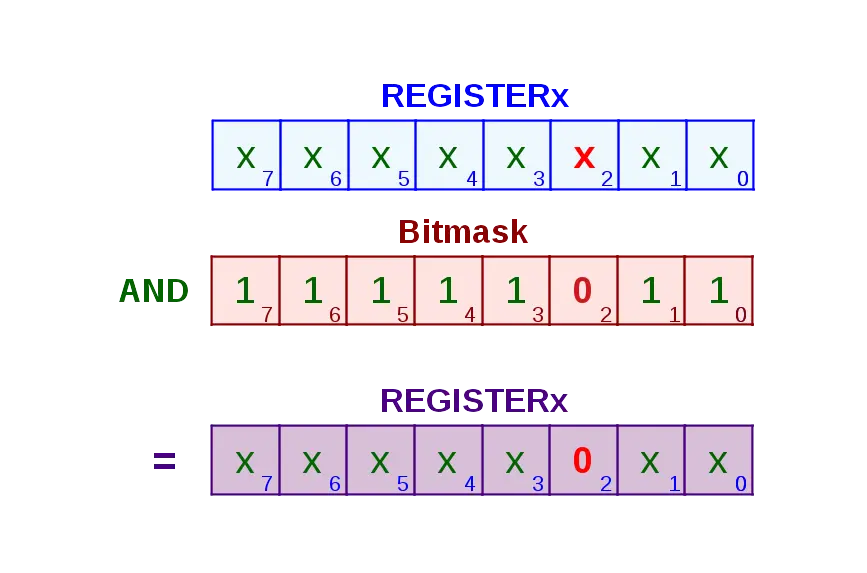
This can be achieved with the following code:
REGx &= 0b11111011;
Or you make it simpler with:
REGx &= ~0b00000100;
Register memory addresses
With some basic understanding of how to manipulate bits in memory you next need to find the right register addresses. For this you need to start looking into the data sheet of your boards microcontroller.
In my case it was the ATmega328 on my Arduino Uno board. First I looked for the memory position for D13, the build-in LED in the data sheet.
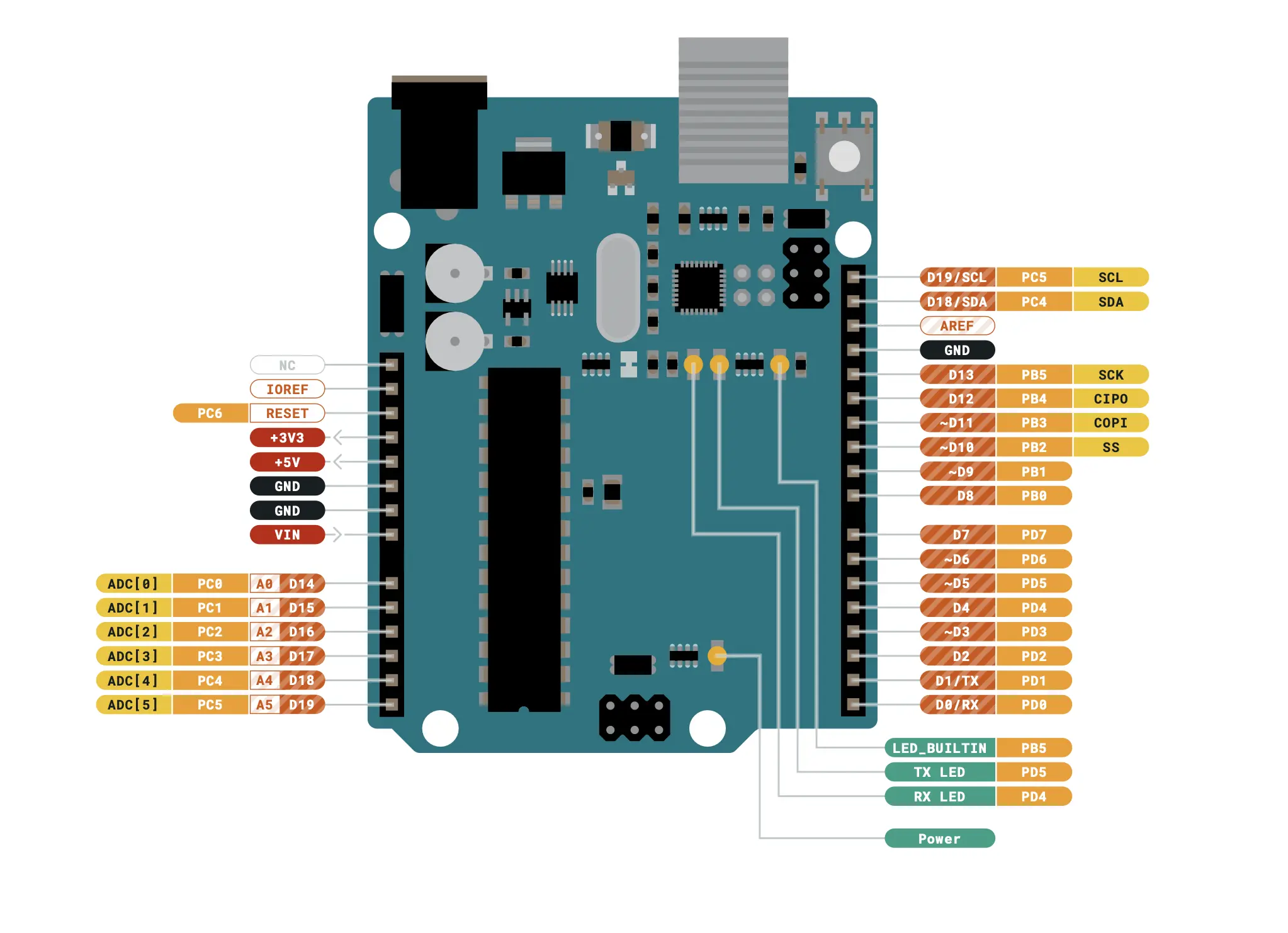
Image by Arduino Uno Store from arduino.cc
Here you can see that D13 is also PB5, which translates to Port B - number 5. Next we need to take look into the data sheet.
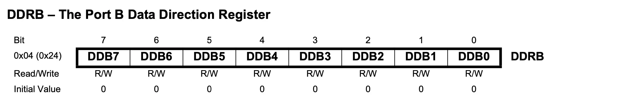
The first thing you want to do is to configure the DDRB register and set the DDB5 bit. With this you set PORTB5 as an output pin.
Turn on the lights
To active the pin and turn the light on you need have to set the PORTB register for number 5.
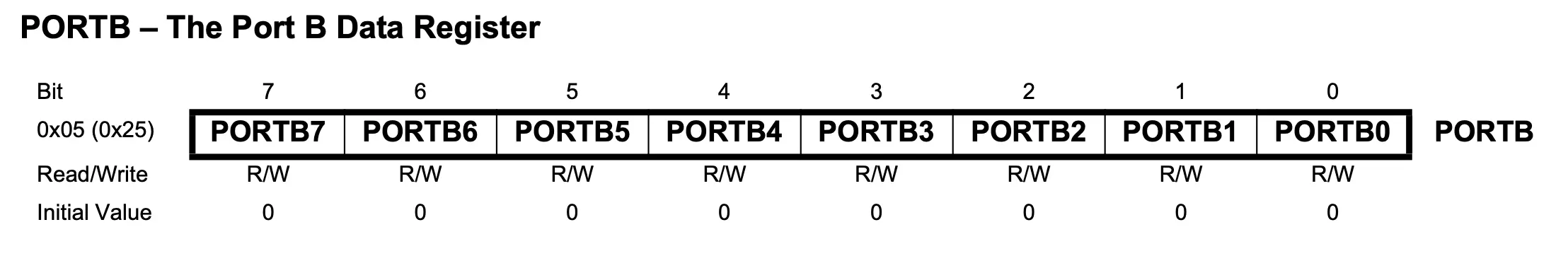
PORTB = PORTB | (1 << PORTB5);
To unset the bit you use the bit mask again as following:
PORTB = PORTB & ~(1 << PORTB5);
Now we use the delay helper function (util/delay.h) to make the clock counting delay easier.
The final program should look something like this:
#include <avr/io.h>
#include <util/delay.h>

int main(void) {

    // set PORTB5 as a output
    DDRB = DDRB | (1 << DDB5);

    while(1)
    {
        // set PORTB5
        PORTB = PORTB | (1 << PORTB5);

        // wait
        _delay_ms(1000);

        // unset PORTB5
        PORTB = PORTB & ~(1 << PORTB5);

        // wait some more
        _delay_ms(1000);
    }
}
Build process
If you want to try to build the code without the Arduino IDE, you can do that by using some command line tools. On Mac you can use brew to install the avr-gcc compiler, avr-binutils and avrdude.
brew tap osx-cross/avr
# removal needed before upgrading
brew remove avr-gcc avr-binutils avr-libc
# avr-libc is now included in avr-gcc
brew install avr-gcc avr-binutils
brew install avrdude
Avrdude
This small utility is used to download/upload/manipulate the ROM and EEPROM contents of AVR microcontrollers using the in-system programming technique (ISP).
avrdude -F -V -c arduino -p ATMEGA328P -P /dev/cu.usbmodem2101 -b 115200 -U flash:w:ledBlink.hex
You will want to change the “/dev/cu.usbmodem2101” to the port name, where your Arduino board is connected.
Makefile
To automate the build process you create a Makefile with the following code:
default:
	avr-gcc -Os -DF_CPU=16000000UL -mmcu=atmega328p -c -o ledBlink.o ledBlink.c
	avr-gcc -o ledBlink.bin ledBlink.o
	avr-objcopy -O ihex -j .text -j .data -R .eeprom ledBlink.bin ledBlink.hex

.PHONY: deploy
deploy:
	avrdude -F -V -c arduino -p ATMEGA328P -P /dev/cu.usbmodem2101 -b 115200 -U flash:w:ledBlink.hex
First the C compiler will produce a machine code file and with the help of avr-objcopy we convert the .bin into a .hex file.
$ make
With the help of avrdude we send the generated .hex file to the microcontroller via USB
$ make deploy
Conclusion
The advantages of using pure C instead of the Arduino IDE with the defined HAL (hardware abstraction layer) is to save a lot of file size. Sure, this is only relevant for production optimizations, but good to keep in mind. I never liked the Arduino IDE and the functionalities, because for me that always felt more like scripting instead of programming.
But on the contrary, if you want to build a quick prototype for a new idea, it’s faster and more agile to just put together a breadboard with a few code snippets in the IDE and validate your idea. After validation would be the time to rewrite in code for best practices and maybe work on a custom PCB board.
For me this exercise was a fun learning exercise, and maybe you also learned something new. Please let me know if you have any questions or feedback to the article, I would love to hear your thoughts.